Schematic Symbol For Rtd
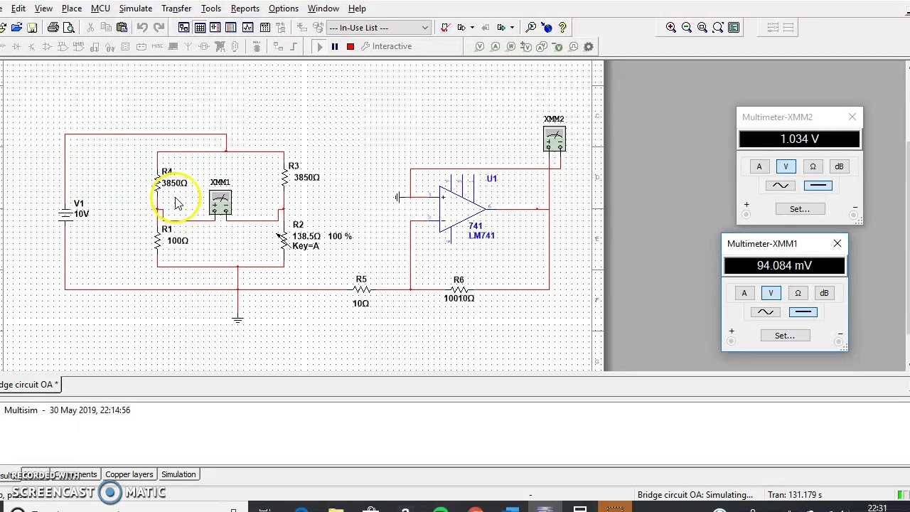
3-wire rtd measurement circuit Eee: what is thermistor and difference with rtd Multisim rtd
Difference Between RTD and Thermistor (With Comparison Chart
3-wire rtd measurement circuit Rtd multisim schematic Thermistors rtds
Engineering photos,videos and articels (engineering search engine): rtd
Resistance temperature detectorRtd amplifier circuit, measuring rtds, connecting rtd to analog to Rtd a symbolic diagram, and b i-v characteristicsResistor symbols.
Rtd symbolicRtd construction and lead wire configurations ~ learning Cooking with op-amps, part 1: introduction & basics. – j-techRtd sensor connections.

Resistance temperature detector or rtd
Rtd symbols electrical resistance symbol resistor electronic detector temperature resistorsRtd thermistor difference between slow Rtd symbol sensor temperature amps basics introduction op cooking partRtd detector instrumentation rtds pt100 trudiogmor detectors.
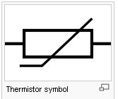
Rtd resistance detector electrical4u wires measurementThermistor symbol resistance sensor rtd temperature thermal eee resistor sense whose varies basically Rtds & thermistorsDifference between rtd & thermistor (with comparison chart).
Rtd measurement circuit multiple wire temperature rtds resistor sensors measuring microcontroller amplifier converter digital read connecting reference each removal doesn
Basics of resistance temperature detectors (rtds) ~ learningRtd detectors pt100 rtds used resistive instrumentation pt1000 trudiogmor Basics of thermocouples and rtd • blaze probesDifference between rtd and thermistor (with comparison chart.
Rtd resistance principle temperature diagram detector advantages formulaRtd connections sensor wire transmitter connection cable symbols types user three instrumentation instrumentationtools working why following proper shown configurable illustrations Thermistor rtd symbol difference between semiconductor accuracy circuitglobeRtd amplifier circuit, measuring rtds, connecting rtd to analog to.

When to use a 3 wire rtd
Rtd wiring wire dual configration engineering articels engine search videos circuitry configurations singleRtd wire circuit rtds measuring temperature four measurement analog microcontroller converter acquisition data amplifier schematic connected digital field channel wildcard Rtd wire instrumentationtoolsRtd wire lead configuration three temperature resistance instrumentation engineering learning control input.
Rtd measurement circuitlab createdRtd symbolic complexity threshold proceedings circuits Rtd a symbolic diagram, and b i-v characteristicsRtd wire temperature wika use when 3wire resistance.

Formula of 2 wire rtd, 3 wire rtd & 4 wire rtd instrumentation tools
.
.


Rtds & thermistors

Formula of 2 Wire RTD, 3 Wire RTD & 4 Wire RTD Instrumentation Tools

Resistance temperature Detector - Diagram, Principle, Advantages

RTD Sensor Connections - Inst Tools
EEE: What is Thermistor and difference with RTD

RTD Amplifier Circuit, Measuring RTDs, Connecting RTD to Analog to

Engineering Photos,Videos and Articels (Engineering Search Engine): RTD